Lab 4: Counters and Clocks
On receiving an interrupt, decrement the counter to zero.
— “Count Zero” William Gibson
In digital systems, counters are often used to record the working status of the system. This lab reviews the working principle of counters. By introducing the working process and design methods of several simple counters, as well as the use of the development board’s system clock, students will learn the design of counters and the working principle of timers.
Up Counters
A simple counter can be constructed using flip-flops. Figure counter01 is a 3-bit binary asynchronous up counter consisting of three D flip-flops triggered by rising edges, i.e., at each rising edge of Clock, the counter outputs \(Q_2Q_1Q_0\) plus 1.
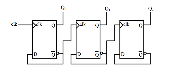
Fig. 22 3-bit binary up counter
Figure counter02 is the state transition diagram of this 3-bit binary asynchronous up counter.
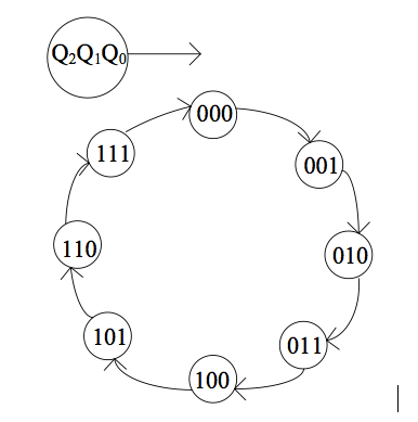
Fig. 23 3-bit binary up counter state diagram
You can also add “clear” and “set” pins to the D flip-flop to form a binary asynchronous up counter that can clear and set values. Please design and verify this circuit yourself.
Down Counters
D flip-flops can also be used to construct down counters. Figure counter03 shows a 3-bit binary asynchronous down counter consisting of three D flip-flops triggered by rising edges.
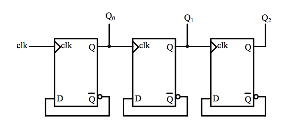
Fig. 24 3-bit binary asynchronous down counter
Figure counter04 is the state transition diagram of this 3-bit binary asynchronous down counter.
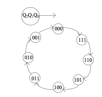
Fig. 25 3-bit binary down counter state diagram
The Verilog language can be used to easily construct counters. Table counter01 is a 3-bit binary down counter, and similar code can be used to construct an up counter.
module vminus3(clk,en,out_q);
  input  clk;
  input  en;
  output reg [2:0] out_q;

  always @ (posedge clk)
    if (en)   out_q <= out_q -1;
    else   out_q <= 0;
endmodule
list-counter01 The simulation diagram of the down counter constructed is shown in Figure fig-countersim.
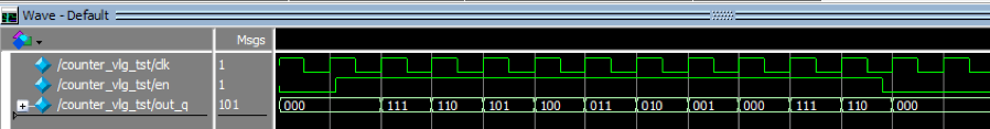
Fig. 26 Simulation diagram of down counter
Timers
If a clock with a fixed period is input to the clock input port of the counter, then the counter becomes a timer.
The purpose of this lab is to learn how to use clock sources on FPGA development platforms and to learn timer design by combining counter design methods.
Clock signals on the development board
The DE-10 Standard development board provides four external input clocks with a frequency of 50MHz for the Cyclone V SOC FPGA, all of which are available for user use. In addition, a 25MHz clock is provided for the HPS on the open platform, as shown in Figure fig-clock01.
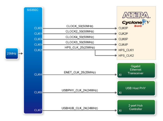
Fig. 27 Development board clock connections
The pins connecting each clock to the FPGA and HPS are shown in Figure fig-clock02:
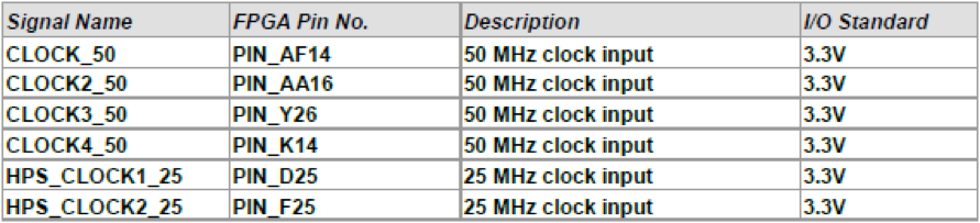
Fig. 28 DE10 Standard clock pins
By using this clock signal as the clock signal for the counter, a timer can be constructed:
Generate desired clock signals
Using the 50MHz clock signal and timer provided on the development board, we can design any clock signal we need. The following example is reference code for generating a clock signal with a period of 1 second. In this example, clk is the system clock, and clk_1s is the clock signal with a period of 1 second.
always @(posedge clk)
  if(count_clk==24999999)
  begin
    count_clk <=0;
    clk_1s <= ~clk_1s;
  end
  else
    count_clk <= count_clk+1;
Please read and understand this code segment, and consider how the width of the variable count_clk should be set to meet the counting requirement of \(0 \sim 24999999\).
Lab check-in contents
On-Board Lab (basic):
Please implement a timer on the DE10-Standard development board and display the result directly on a seven-segment LED display in decimal format.
Using the 50MHz clock on the development board, first design a frequency divider with an input of 50MHz clock and an output of a 1Hz clock signal with a period of 1 second. Then use this new 1Hz clock signal as the clock signal for your design to perform counting.
The timer must have start, pause, and reset functions. It should count from 00 to 99, and after reaching 99, it should restart counting from zero. The count value should be displayed on the seven-segment display using two digits.
At the end of the timing, you may have a specific LED flash for one clock cycle to indicate the timing has ended.
On-Board Lab (advanced):
Implement an electronic clock on the DE-10 Standard development board. The clock must be able to display hours, minutes, and seconds. It should also have the following functions: time adjustment; alarm (LED flashes at a specific time); stopwatch (provides 1/100th of a second accuracy, can be stopped and restarted), etc.
Online test
Counter cascading
Online test
Hamming code error correction