Lab 9: Character Input Interface
*The input for first-generation computers was nothing more than a glorified typewriter keyboard, while output relied on high-speed printing or visual displays. HAL could do these things when necessary, but he interacted with his fellow humans mostly through speech. *
— 2001: A Space Odyssey, Arthur C. Clarke
This experiment will utilize the keyboard and display functions implemented earlier to build a simple character input interface. Through the implementation of this system, we will gain a deeper understanding of the interaction between multiple modules and the design of interfaces.
Character Display
From previous VGA image display experiments, we have learned that graphical interfaces require a large amount of resources. Implementing high-precision, high-resolution graphical interfaces on FPGAs can be somewhat resource-intensive. However, the resources available on FPGAs are much richer than those available on first-generation PCs decades ago. It is not difficult to use FPGAs to implement a simple character input and display interface.
The character display interface only displays ASCII characters on the screen, which requires relatively few resources. First, ASCII characters are represented by 7 bits, with a total of 128 characters. In most cases, we use 8 bits to represent a single character, so most systems reserve 256 characters. We can pre-store the character font bitmaps for these 256 characters in the system, as shown in Figure fig-ascii.
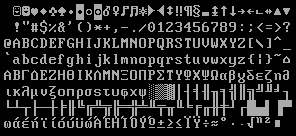
Fig. 67 ASCII characters font
Each character here is 16 pixels high and 9 pixels wide. Therefore, a single character can be represented by 16 9-bit numbers, each representing a row of the character, with the corresponding pixel displayed in white when it is 1 and black when it is 0. Therefore, we only need \(256\times 16 \times 9 \approx 37\) kbit of space to store the entire bitmap. Students can use high-level languages to generate bitmap files themselves. We also provide a bitmap text file <../resources/vga_font.txt>_ that can be read with the $readmemh statement, in which every 3 hexadecimal numbers (12 bits in total) represent a single character line, and the leftmost pixel of the 9 pixels in that line is the lowest bit of the 12 bits ( please note the order of high and low bits ), and so on. The highest 3 bits are always 0. Each character has 16 lines, totaling 256 characters.
For example, the ASCII character A is encoded as 41h (decimal 65). Therefore, the address corresponding to its character pattern is \(16\times65=1040\) (text files start from line 1, so it is on line 1041). Taking the fourth line of the character A as an example, the file stores 038h, which corresponds to 0000 0011 1000 in binary. The least significant bit is 0, so the first pixel on the left is 0, and the fourth to sixth pixels from the left are 1. As shown in Figure fig-chara, the colors are reversed for convenience of display.
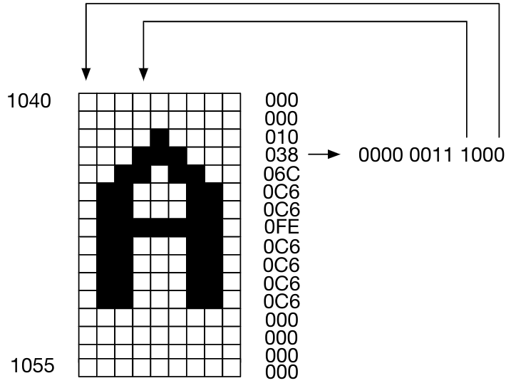
Fig. 68 The relationship between the character font “A” and the memory
With the character pixels matrix, the system no longer needs to record the color information of each pixel on the screen, but only needs to record the ASCII characters displayed on the screen. When displaying, determine which character should be displayed based on the current screen position, then find the corresponding character pixels matrix to complete the display. For a \(640×480\) screen, it can display 30 rows (\(30×16=480\)) and 70 columns (\(70×9=630\)) of ASCII characters. The system’s display memory only needs to be \(30\times70\) in size, with each cell storing 8 bits of ASCII characters. In this way, our character display memory only needs 2.1 kBytes, plus 6.144 kBytes for the dot matrix, for a total of less than 10 kBytes of storage, which is sufficient for the FPGA chip.
System Design
Scan display
We have already implemented the VGA control module, which can output the current scanned row and column position information. With a few modifications, we can make it output the coordinates of the current scanned position corresponding to the \(30\times 70\) character array ( \(0\leq x \leq 69\) , \(0\leq y\leq 29\) ). Using these coordinates, we can query the character memory to obtain the ASCII code of the corresponding character. Using the ASCII code, we can query the corresponding pixel matrix ROM, and then, based on the row and column information of the scan line, we can know which pixel within the character is currently being scanned. At this point, we can choose to output white or black based on whether the bit corresponding to that pixel is 1 or 0.
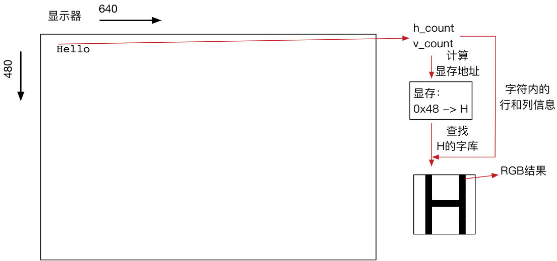
Fig. 69 Character display flowchart
We summarize the process as follows:
Based on the current scan position, obtain the x and y coordinates of the corresponding character, as well as the row and column information scanned into the single character dot matrix.
Based on the x and y coordinates of the character, query the character display memory to obtain the corresponding ASCII code.
Query the dot matrix ROM based on the ASCII code and row information within the character to obtain the 9-bit data of the corresponding row.
Retrieve the corresponding bit based on the column information within the character and set the color based on that bit. Here, you can display white characters on a black background or other colored characters. You only need to set the background color and character color according to your needs.
Since the scanning frequency of VGA is 25 MHz, the time taken to scan each pixel is very short. Therefore, careful timing design is required to complete this series of operations within the time taken to scan one pixel. First, it is difficult for FPGA to complete multiplication and division in such a short time. Therefore, when designing, it is necessary to reasonably select the size and addressing method of the memory, and simplify the address calculation to simple counting and logical operations. Second, we need to query multiple memories for each pixel, and the query method for each memory needs to be reasonably designed: should we use RAM or ROM? Should we use rising edge readout or falling edge readout? All of these may affect the final performance of the system. Displays with performance issues may show colored edges or blurring, which indicate potential problems with the system implementation.
Do not use registers to implement large-capacity storage
If you use registers to implement the required memory instead of the on-chip M10K or MLAB, it may consume a large amount of resources, causing FPGA resource shortages and significantly increasing compilation time.
Memory read/write
For keyboard input, we can reuse the keyboard controller we implemented earlier. When there is input from the keyboard, we rewrite the character display memory, writing the ASCII code corresponding to the key to the appropriate location in the display memory, so that the input is directly reflected on the screen.
Pay attention to memory read/write operations
The character video memory that stores ASCII codes is frequently read at high speed by the VGA scan module, while the keyboard module needs to write to the video memory. It is important to ensure coordination between the two modules.
Lab check-in contents
On-Board Lab: Implement a character interactive interface
Implement an interactive interface that allows keyboard input and displays output on a VGA monitor. The interface implementation requirements can be referenced from the DOS character interface, Windows command line, or Linux character terminal.
Support input of all lowercase English letters and numbers, as well as symbols that can be entered without using the Shift key.
When a key is held down continuously, the character is repeated.
After reaching the end of the line, the input automatically wraps to the next line; pressing Enter also causes a line break.
Optional extension requirements (only five or more need to be completed to achieve full marks)
The cursor can be displayed. It is recommended to use a flashing vertical or horizontal line as the cursor.
Supports the BackSpace key to delete characters before the cursor.
After deleting to the beginning of the current line with BackSpace, pressing BackSpace again deletes the Enter key, leaving the cursor after the last non-empty character on the previous line.
Supports automatic scrolling: after reaching the last line, pressing Enter creates a new blank line, and all previously entered lines automatically shift up one line.
Supports Shift key and uppercase/lowercase character input.
Supports moving the cursor using the arrow keys.
Displays the command prompt at the beginning of the line.
Even cooler effects
Interested students may also consider how to implement colored characters, draw ASCII art, or achieve a character rain effect similar to the beginning of the Matrix.
Minimum requirement
This experiment is quite challenging. The minimum requirement is to be able to display pre-set characters on the monitor, but only meeting the minimum requirement will not earn you full marks.
Online test
Simple Turing machine implementation